English
 Pусский
 عربي
عربي It always starts the same way. The morning shift kicks off with smooth motor hum, clean bonding, and perfectly flat reels. By 10:30 a.m., however, the operator is already chasing gauge variation. By noon, there’s a web break just before the winding station. These aren’t freak accidents — they are systemic symptoms that, left unaddressed, can quietly drain over 15% of your annual throughput, according to an internal review of packaging conversion losses shared at a TAPPI PLACE conference.
While many converters treat such hiccups as “part of the process,” our experience working alongside packaging facilities across Southeast Asia and Eastern Europe reveals a different truth: the majority of day-to-day instability springs from just a handful of root causes. Understanding them is the fastest way to turn a temperamental line into a predictable profit center — and it often requires far less capital than a full rebuild.
1. The Real Cost of Melt Temperature Swings
Temperature deviation is the silent saboteur. Even a ±3°C overshoot across the die width can alter polymer viscosity enough to create uneven coating weight, edge bead inconsistency, or pinhole-sized voids that only show up after slitting.
Root cause often lies deeper than a faulty thermocouple. In many legacy lines, barrel heating zones react too slowly because the PID loops haven’t been re-tuned after a resin switch or screw modification. We’ve measured cases where the actual melt temperature at the die lip lagged behind the controller reading by 11°C — enough to shift adhesion performance from “acceptable” to “scrap.” Running LDPE at 320°C, for instance, can push the resin toward degradation, generating gel particles that block the die gap over time.
Stabilization strategy
-
Perform a step-change calibration test every six months: raise the setpoint 10°C, log the time-to-stability, and compare across zones. Any zone requiring more than 30% additional time needs loop tuning or heater inspection.
-
Install a melt-temperature probe at the adapter, not just in the barrel. ISO 11357-based thermal analysis can then correlate real-time readings with DSC data to avoid oxidation thresholds.
-
When you’re looking for long-term consistency, an integrated coating line platform with real-time melt analytics eliminates much of the manual chasing.
2. When a Worn Screw Becomes a Profit Leak
Gradual screw and barrel wear rarely triggers an alarm. Operators simply compensate by nudging RPM up or adjusting the die bolt profile. Over 18 months, that silent drift can cost a plant upwards of $50,000 in additional resin consumption and excessive gauge giveaway.
The wear mechanism is straightforward: filler concentrates (TiO₂, CaCO₃) and recycled content act as mild abrasives, eroding the root diameter and increasing the flight clearance. Once clearance passes 0.3% of the screw diameter, melt homogeneity begins to suffer. The symptom is often misdiagnosed as “inconsistent resin lot.”
What you can do this week
-
Extract a purging sample and measure specific throughput (kg per screw revolution). A drop greater than 7% from the baseline recorded after the last rebuild strongly suggests excessive wear.
-
Use a portable borescope to inspect the barrel’s feed zone; grooved sections are especially prone to pitting.
-
Specify bimetallic barrels and screws protected with nickel-based tungsten carbide coatings for any abrasive blend exceeding 15% filler content. This one material decision typically triples the service interval.
3. Web Tension: The Downstream Domino
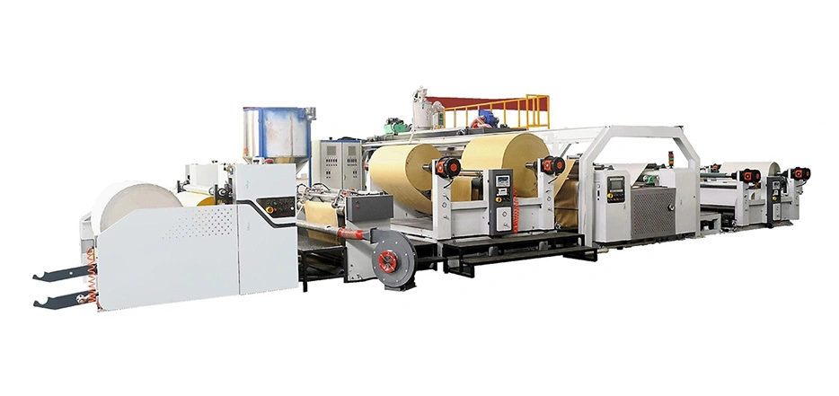
A stable polymer melt means nothing if the substrate flutters. Web breaks, wrinkling at the nip, and cyclic registration errors in downstream printing frequently trace back to either a tension setpoint mismatch or a load cell that’s drifted out of calibration.
The tricky part is that the optimal tension window shifts with substrate changes. A 12-micron metallized PET requires roughly 18–22 N/m to avoid bagginess, whereas a 40-gsm kraft paper might need 120–140 N/m. When a converter runs multiple structures per shift without resetting dancer parameters, the first 300 meters of every new roll become a risk zone.
A field-tested routine
-
Before threading a new roll, record the unwind brake air pressure and verify load cell zero-point against a known static weight.
-
Build a one-page “tension recipe” card laminated at each unwind station, listing the ideal tension range for your top five substrates. Keep it visual — it gets used more.
-
If you’re still battling sudden tension spikes after verifying the mechanical side, the culprit is often in the drive synchronization. A line control architecture that synchronizes unwind, nip, and winder drives via a common motion bus prevents the subtle speed hunting that analog signals often miss.
4. The Adhesion Puzzle No One Has Time to Solve
“Why did it peel?” is the question that ends many Friday afternoons. Sometimes the answer lives in the substrate surface energy. Other times, it’s ozone concentration, air-gap distance, or the cooling-roll temperature profile.
A practical framework we often share with technicians breaks adhesion troubleshooting into three checkpoints:
-
Substrate readiness: Use dyne pens (minimum 38 dyn/cm for polyolefins right at the nip) immediately after the corona treater. Surface treatment decays quickly; the measurement must happen in-line, not on a rolled sample.
-
Oxidation window: For standard LDPE coating at 15–30 g/m², an air gap of 120–150 mm combined with an ozone concentration of 25–35 g/m³ typically yields peel strengths above 2.5 N/15 mm on aluminum foil. Shortening the air gap below 80 mm can halve the bond strength.
-
Thermal shock at the nip: The cooling roll’s surface temperature should stay between 15°C and 22°C for most polyolefins. Above 28°C, the quench rate slows, crystallinity increases, and hot-tack becomes unreliable.
When these three variables are data-logged — not just checked once a month — patterns emerge fast. Shifts that never meet the peel specification are often running the cooling water 5°C warmer than the SOP specifies, simply because someone adjusted the chiller setting last summer and never reverted it.
5. Electrical Noise: The Ghost in the Machine
It’s the least visible culprit. A poorly grounded extruder barrel or a VFD cable routed parallel to a thermocouple signal wire can inject 50–60 Hz noise into the temperature feedback loop. The controller then oscillates by fractions of a degree — invisible on a bar-graph display but enough to create visible polymer lumpiness after the die.
One simple diagnostic: set your data acquisition to log at 50-millisecond intervals for five minutes. If you see high-frequency sawtooth patterns superimposed on a stable average, you’re hunting electrical noise, not thermal instability. The fix can be as straightforward as replacing a missing grounding strap on the die body or re-routing signal cables in the junction box.
Building Stability In, Not Just Patching It
A line that runs stable shift after shift is never the result of heroic operator intervention. It’s engineered through thoughtful component selection and a control philosophy that treats variability as information, not noise.
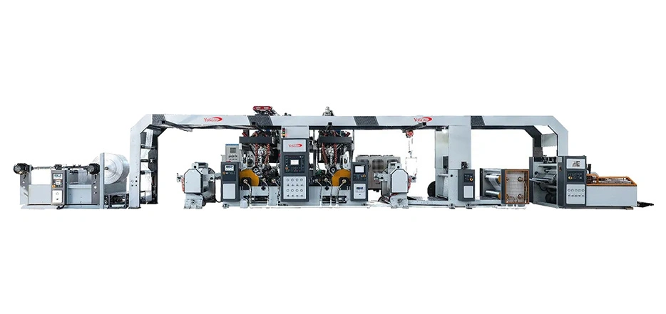
If the checklist above feels uncomfortably familiar — if your team is spending more time nursing the line than improving it — it may be time to evaluate a platform designed from the ground up to address these exact failure modes. Yongxu’s coating and laminating systems, for example, integrate a thermal regulation algorithm that learns from historical melt behavior, a tension control loop that auto-adjusts for each reel’s diameter profile, and a drive architecture that isolates signal interference from the control layer. The result is fewer morning chaos sessions and more predictable, saleable output by mid-afternoon. You can explore the technical specifications of Yongxu’s intelligent coating line solution to see how its architecture eliminates the common pitfalls described here.
Stable production isn’t a mystery. It’s a measurable, replicable set of conditions. And it’s far more accessible than most operators have been led to believe.
Disclaimer: The troubleshooting guidance provided in this article is based on general industry practice and field experience. Specific machine parameters should always be verified against the OEM manual. Performance outcomes depend on material properties, maintenance history, and ambient conditions.